
2002 Project - MR19 Restoration
by Jeremy Winkworth
I was going to take a year off in 2002 but when I found a nine inch crack in the engine block of my Fairmont MR19, something had to be done. I wanted to keep the car looking as original as possible so a mechanical and electrical restoration with minimal cosmetic changes was the plan.
First, a little history: This car, a Fairmont MR-19-A-3, was originally purchased in May of 1956 by the Detroit, Toledo and Ironton Railroad Company (DT&I), now known as the Indiana and Ohio Railroad. It was shipped on June 8, 1956 to Flat Rock, Michigan. It became DT&I car #1541. The engine number is 98004, shown on the build sheet as an RO-C-4 model. Note that some of the engine components on reversing cars are not standard ROC. Examples of such include the crankshaft, bearing housings, Weathershield timer casting, belt-side flywheel and of course, the two belt pulleys. There are probably no more than a dozen reversing cars left in original condition. Railroads got tired of the complexity and extra cost of a reversing car. Many replaced the engine and mechanicals with standard M19 components.
|
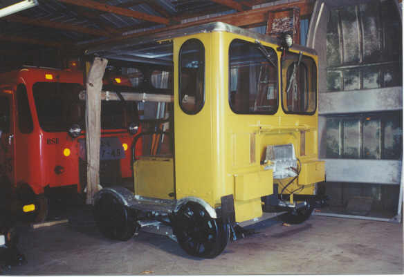
Here is the car in "as bought" condition. It looks good but the electrical system was in poor shape, the belts were very well used and it was covered with dirt and grease inside the engine compartment. A few of the mechanical components needed work. Then there was the crack.... |
|
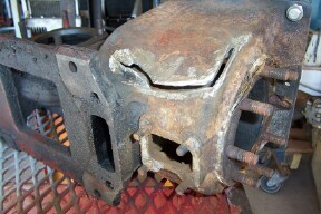
Upon finding the crack in the engine block, I whipped out the engine and took it over to my engine restorer. Here's a photo that he took of the crack, ready for welding. This type of crack is usually caused by the water freezing when the engine is overfilled. Actually, the melting of the frozen water caused the crack. This happened before I got it, I might add. |
|
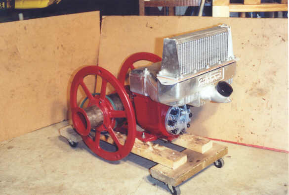
6 months later the engine looked like this. New rings, gaskets and paint were all the parts that were needed. Looks good, does it not? |
|
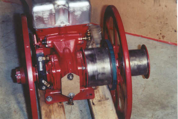
Here are the two belt pulleys on a reversing engine. The right one is for forward travel, the left for reverse, via a gearbox. Getting the pulleys off one of these engines, particularly one has has not been touched for many years can be difficult. Note the generator pulley between the two belt pulleys. |
|
This is the brake-light switch, located close to the bottom of the brake lever. I used a bullet-type switch from an auto store (NAPA Part # SL779) mounted in a bent eye bolt, which goes through some angle aluminum. It can be adjusted if necessary. I located it right at the bottom of the lever to keep it out of the way. |
|
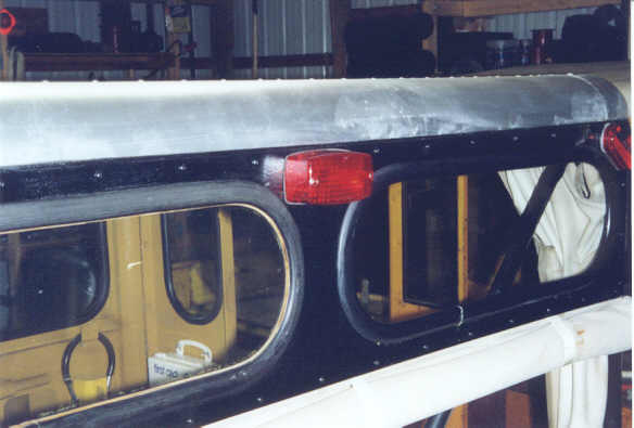
I mounted a rectangular brake light on the rear of the car at the top. This was a standard light from an auto store with the 12V bulb replaced by a 6V one. I wired to both filaments in the bulb so it's bright enough to get your attention but it doesn't look out-of-place on the car. |
|
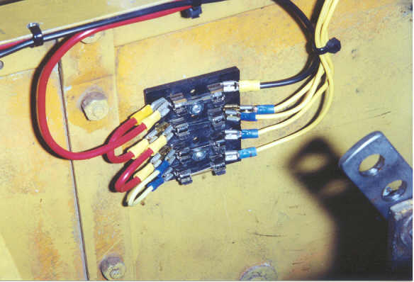
Here's the fuse block. Fairmont cars did not contain fuse blocks as original equipment. However, there is a real risk of shorting out and burning up the wiring so if you are rewiring, it would recommend using fuses. I used mostly #14 wire with #10 for the generator and main lead. Fuses going down from the top are (1) generator, (2) lights, (3) wipers and (4) ignition. It is located on the tunnel wall above the belt. |
|
It looked like there had been a bracket for holding the reversing gearbox in place but it was gone and replaced by a home-built one that resulted in very poor alignment of the link to the gearbox. I fabricated a sturdy bracket, shown here and painted it grey. |
|
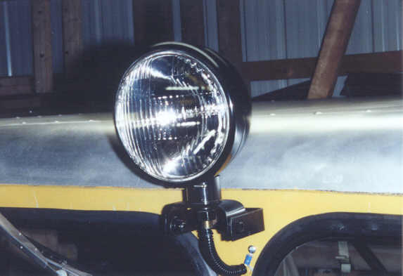
Bil Kinney tipped me off that a New Holland tractor headlight (Part # 310066F) looks very close to some Fairmont headlights. It's 6" diameter and made of almond-painted steel but I painted it black. They are available in 6 and 12V versions. The bulb is Westinghouse NOS that I had in stock. Below the light is the adaptor that you need (Part # E0NN13A097AA). |
|
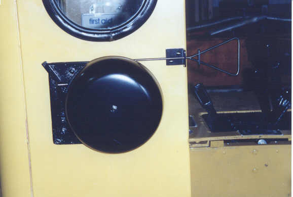
I didn't want to add horns, so to be NARCOA-legal a bell was needed. This bell came from the W.L.Jenkins Company, who supplied bells to Fairmont for use on speeders. It's a model 60 steel gong, 8". |
|
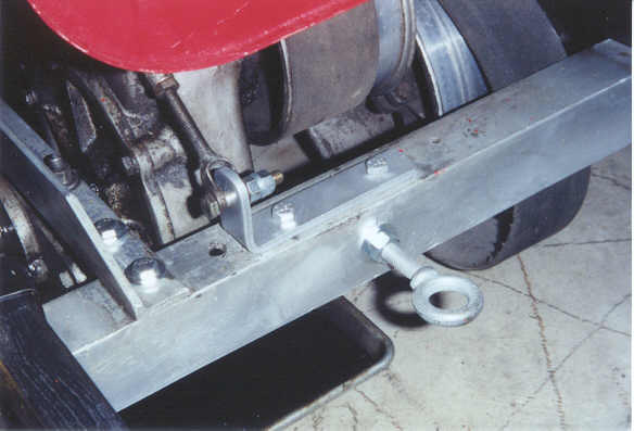
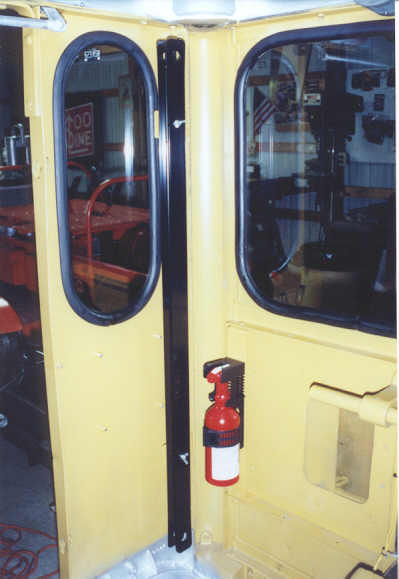
Another NARCOA necessity is a tow bar. This toolbar is a piece of 1"x 2"x1/8" steel stock with holes for 3/4" pins, painted gloss black. I chose to store it vertically on the side of the cab. There are two L-shaped brackets that hold it. Note the fire extinguisher, also a required item. Thank you Steve Paluso for letting me know that the curtain rod brackets were upside-down. |
|
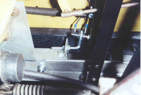
Because the control panel on a reversing car is over to the side of the engine tunnel cover, the control rods are very different to those on a regular car. They go back from the control levers to the mechanism shown here. This shifts the movement about 3 inches towards the center of the car. I removed all this, painted it and made sure it was well-lubricated. |
|
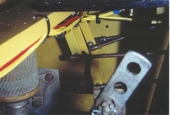
Then other rods go forward to the timer and throttle valve (so there's a total of 4 rods instead of the usual 2). Here are the 4 rods - the two at the back go to the levers, the two at the front go to the engine. |
|
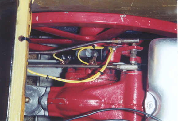
Here are the rods attached to the timer and throttle valves. Note the very small space between the two levers. The nuts that fasten the rods to the levers are within 1/16 inch of each other. There's a lot packed into a small space on these cars. |
|
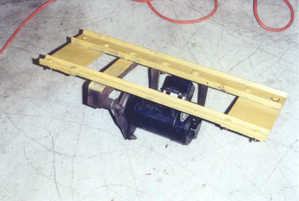
The generator is suspended from the roof of the engine tunnel on a sturdy metal frame. This frame goes ahead of the control panel. The generator belt adjustment is shown on the front left under the frame. |
|
|
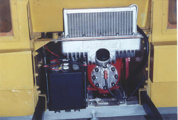
Here's where the engine is fastened to the frame on a reversing car. It's about 3 inches further right that a regular ROC engine would be. The frame member holding the engine that goes through to the rear of the car is on the right, not the left, to stay clear of the two belts. The battery is at the front of the car on the left. |
|
|
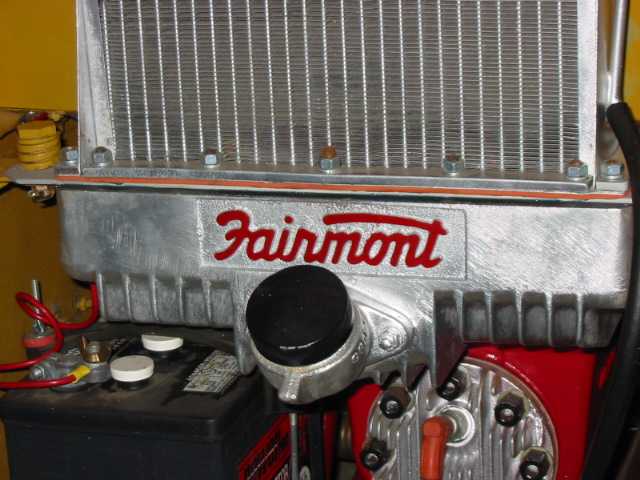
The ceremonial painting of the Fairmont logo on the engine marks the final activity of the project. Well, I need to stencil the edges of the roof with railroad name and car number too. |
The wheels, bearings, axles, brakes and other mechanisms were all in good shape, except for the pull rod and strap for the forward belt lever. Replacement of these is described on another page (click here). I ran out of time to test out the car before winter arrived so a test run is necessary sometime. And that was 2002's project..........
Last Edited 28 January, 2018